
EK Box Isolator Switches Enclosed Cam Switch
Konrak’s isolator Switch with EK enclosure box, Padlockable handle for Multiple Lock is an enclosed cam switch that provides cam-switch functions inside a protective enclosure. It is supplied with a padlockable handle for multiple locks. Typical installations cover dusty or wet areas. As with the whole Konrak range, it is manufactured to IEC/EN 60947-3.
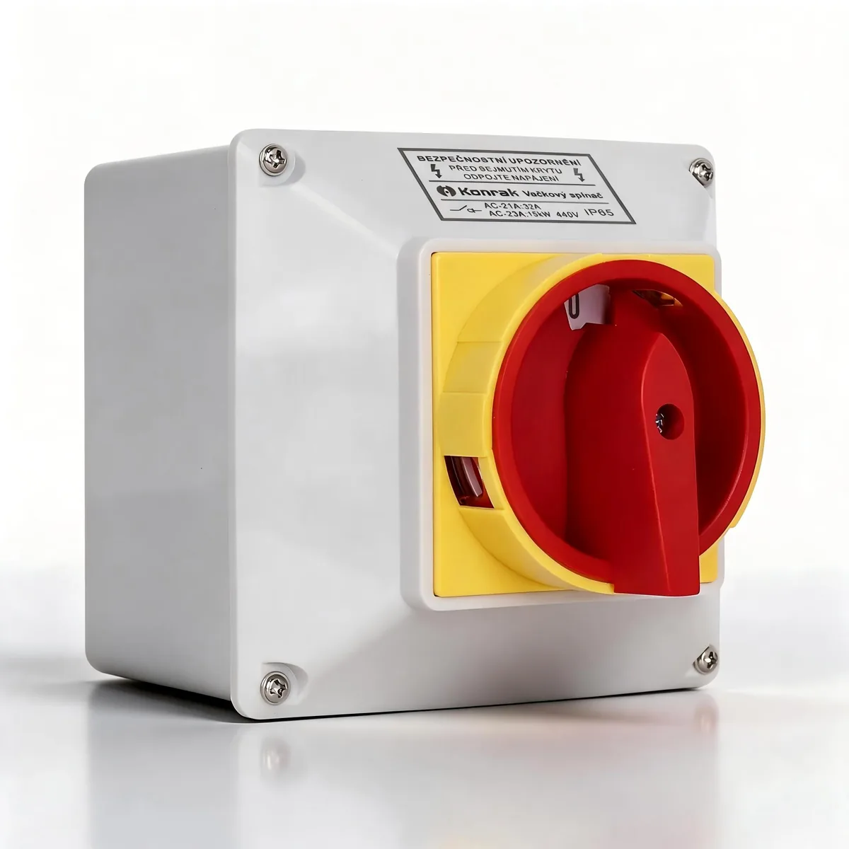
The LW26 cam-switch range
The LW26 series cam switches deliver a versatile solution for the vast majority of cam switch applications. Featuring diversified contact designs, a full range of contact materials and multiple terminal options, they can be deployed as control switches, instrument switches and motor control switches, and are also fully compatible with electronic circuits and harsh corrosive environments, in full compliance with IEC 60947-3 standards.
The switch stage serves as the universal base module for all models, supporting a maximum of 2 contacts per unit. Terminals are fully accessible from the side to simplify field wiring. The LW26 series adopts open terminal design for easier wiring operations, and selected current rating models are certified with anti-accidental finger contact protection, meeting the requirements of EN 50274, VDE 0660 Part 514 and DGUV V3 standards.
Standards EN IEC 60947-3:2021 and EN IEC 60947-1:2021 · certified TUV.
One range, eight switch functions
The same LW26 cam-switch platform covers all of the switching duties below. The function of a given model is set by its contact arrangement and face plate.

ON-OFF
Two-position on/off switching, 60° or 90°, with or without spring return.

Main
Main-switch duty, 90°, padlockable handle (GSY).

Emergency Off
Emergency-off duty for the rapid disconnection of machinery, 90°, padlockable.
Instrument
Voltmeter, ammeter and volt-ammeter selection, with or without OFF.
Motor
Dedicated motor control: reversing, multi-speed, star-delta, auxiliary phase.

Control
Control-circuit switching: code, gang, position indication, spring return.

Multi-Step
Multi-position step switching, 2 to 6 steps, with or without OFF.

Changeover
Changeover between two sources or loads, with or without OFF, 60°/90°, up to 12 poles.
Technical specification
Rated values for the LW26 cam-switch range according to EN IEC 60947-3:2021 and EN IEC 60947-1:2021, certified TUV.
| Parameter | Unit | LW26-10 | LW26-16 | LW26-20 | LW26-25 | LW26-32 | LW26-40 | LW26-50 | LW26-63 | LW26-125 | LW26-160 |
|---|---|---|---|---|---|---|---|---|---|---|---|
| Rated thermal current Ith / Ithe / It | A | 10 | 16 | 20 | 25 | 32 | 40 | 50 | 63 | 125 | 160 |
| Rated insulation voltage Ui | V | 690 | 690 | 690 | 690 | 690 | 690 | 690 | 690 | 690 | 690 |
| Rated impulse withstand voltage Uimp | kV | 2.5 | 2.5 | 2.5 | 2.5 | 2.5 | 2.5 | 2.5 | 2.5 | 2.5 | 2.5 |
| Operational current Ie · AC-21A — switching of resistive loads, including moderate overloads (3-phase 440 V) | A | 10 | 16 | 20 | 25 | 32 | 40 | 50 | 63 | 100 | 150 |
| Operational current Ie · AC-22A — switching of combined resistive / low-inductive loads, including moderate overloads (3-phase 440 V) | A | 10 | 16 | 20 | 25 | 32 | 40 | 50 | 63 | 100 | 150 |
| AC-23A — frequent switching of motors or other high-inductive loads (3-phase 440 V) | A | 6 | 15 | 15 | 22 | 30 | 30 | 45 | 57 | 90 | 135 |
| AC-23A (motor power) | kW | 3 | 7.5 | 7.5 | 11 | 15 | 16 | 22 | 30 | 45 | 55 |
| AC-3 — direct-on-line starting, star-delta starting (3-phase 440 V) | A | 4 | 11 | 11 | 15 | 22 | 25 | 30 | 36 | 75 | 95 |
| AC-3 (motor power) | kW | 2.2 | 5.5 | 5.5 | 7.5 | 11 | 12 | 15 | 18.5 | 30 | 37 |
| AC-4 — direct-on-line starting, reversing, plugging and inching (3-phase 440 V) | A | 1 | 3.5 | 3.5 | 6.5 | 11 | 11 | 13 | 15 | 30 | 55 |
| AC-4 (motor power) | kW | 0.55 | 1.5 | 1.5 | 3 | 5.5 | 5.5 | 6 | 7.5 | 12 | 15 |
| Rated short-time withstand current (1 s) | A | 240 | 240 | 240 | 280 | 480 | 480 | 756 | 756 | 1523 | 2000 |
| Size of conductor | mm² | 0.75–2.5 | 0.75–2.5 | 0.75–2.5 | 1.5–4.0 | 1.5–6.0 | 1.5–6.0 | 4.0–10.0 | 4.0–10.0 | 6.0–25.0 | 10.0–50.0 |
Rated utilization categories to IEC/EN 60947-3. Short-circuit protection is provided in conjunction with suitable upstream protective devices.
Switch body and parts name
The switch is built from a common stage module; the body and parts layout differs by current rating.

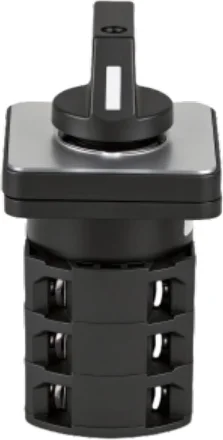
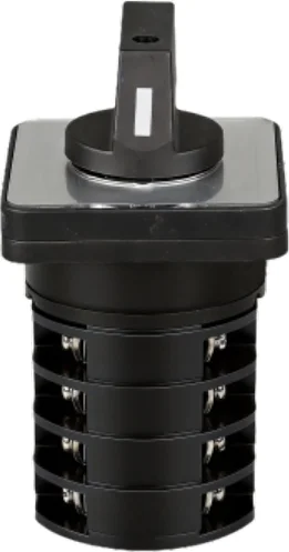
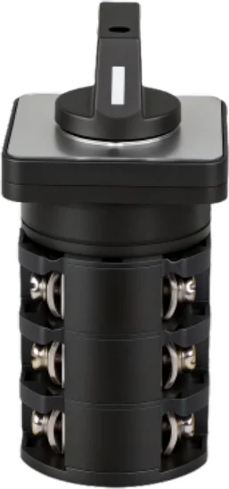
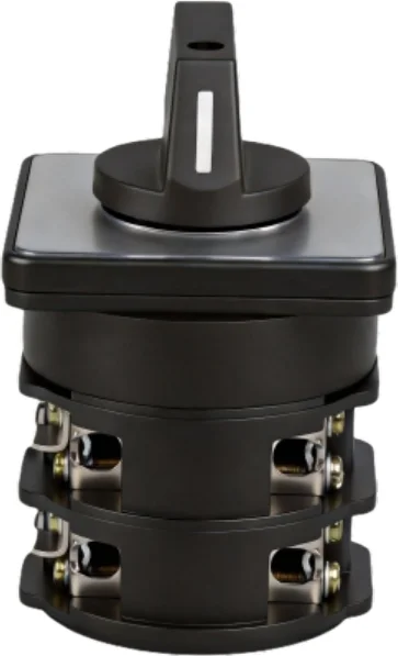
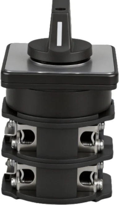


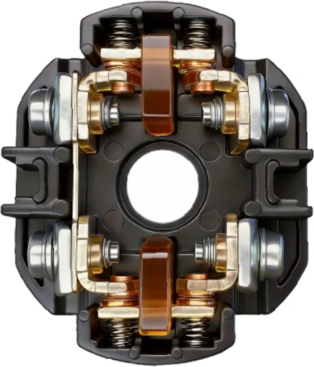
Parts shown: Bottom plate · Side rod · Cam · Cam disk · Switching cell · Terminal screw · Latching mechanism · Mech cam · Limit cam · Mounting plate · Shaft · IP65 gasket · Plate holder · Face plate · Handle
Mounting options
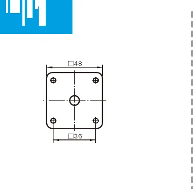
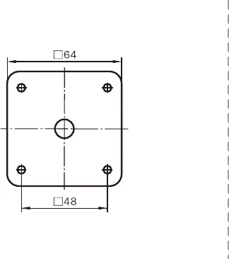
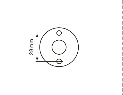
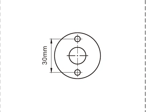
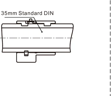
Three mounting systems are available: panel (R), base / 35 mm DIN rail (B) and enclosure (EK). All dimensions are in millimetres.

Panel mounting




Base mounting
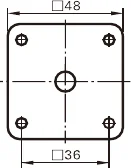

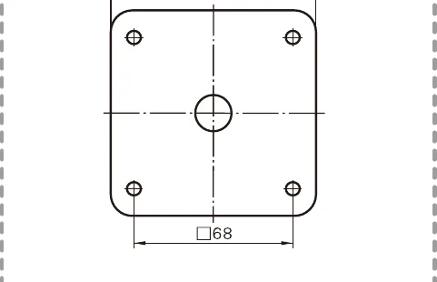

Enclosure mounting
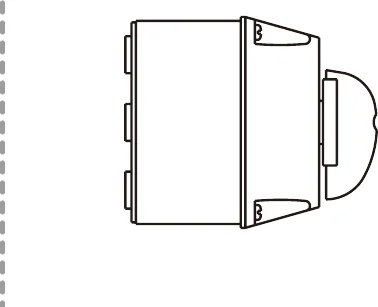
Panel mounting R1–R7 (Ø22–36 mm shafts) · Base mounting B1–B4 (35 mm standard DIN) · Enclosure mounting EK.
Face plate options

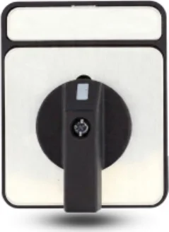
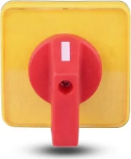

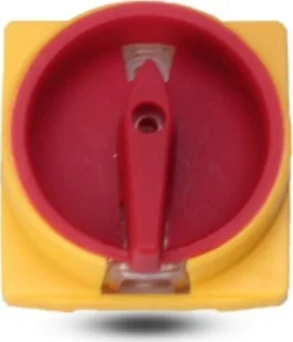
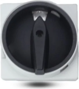
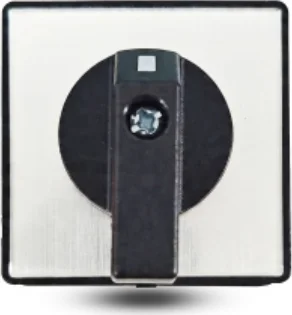
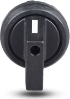
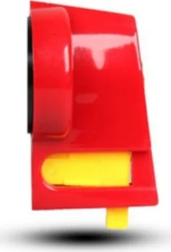
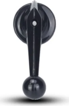
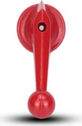
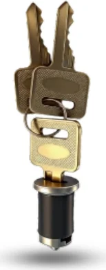
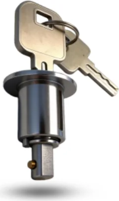
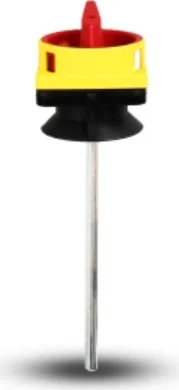
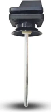
Handle options
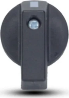
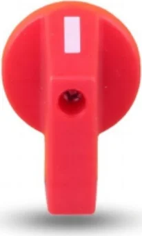


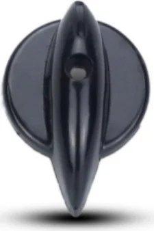

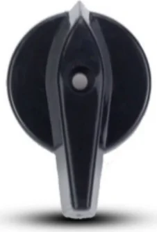
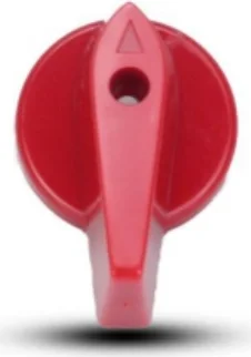

Application scenarios by switch function
The Konrak LW26 rotary cam switch range covers a broad set of switching functions — from simple on/off and changeover duty to motor control, multi-step selection and instrument metering. The applications below are grouped by switch function. All units are AC switches rated to IEC/EN 60947-3.
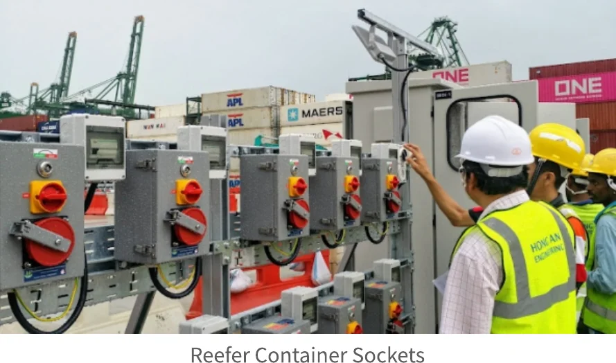

Enclosed Cam Switches
Cam switches supplied in EK enclosures, padlockable versions available.
| Application scenario | Typical applications |
|---|---|
| Local machine isolation | On-machine isolation switches |
| Padlockable maintenance | LOTO on isolated circuits and drives |
| Harsh / wet areas | IP-rated enclosures for dusty or wet places |
| Remote / local switching | Switching away from the main panel |
| Enclosed changeover / isolator | Ready-mounted enclosed switch units |
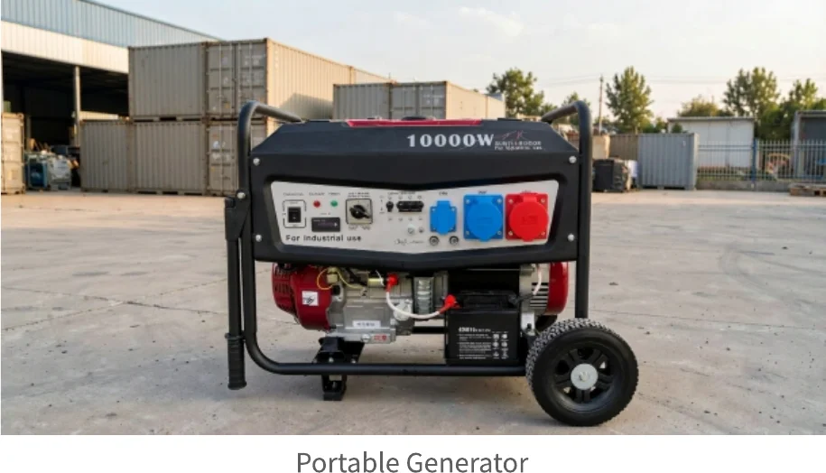
Switch examples pictured in the source datasheet: reefer container sockets, switchboards & main switches and portable generator panels.
Attention
Attention
Before any installation or maintenance operation, disconnect the power supply to the system. Before restoring the power supply, make sure that all connections to the device have been made correctly. Konrak Electric disclaims any responsibility for any damage to things and people caused by non-compliance with the rules described here.
Any improper installation or any tampering of the device may cause serious personnel injury or property damage; therefore the installation and maintenance must be performed by specialised and authorised personnel.
The use of this device is not allowed in environments with a potentially explosive atmosphere, or in the presence of corrosive substances and salt spray.
Need a cam switch for your application?
Tell us the function (ON-OFF, main / emergency-off, changeover, motor, control, multi-step, instrument selector or enclosed), the current rating, the number of poles and the mounting — our team will confirm the right LW26 configuration and can supply samples, OEM branding and bespoke contact arrangements.
Request a Quote Download Datasheet (PDF)