
Konrak RKE DC Isolator Switch
A dedicated DC isolator, not an AC switch re-used. The RKE breaks the DC arc properly with an 8 mm contact gap per pole, handles string voltages up to 1200 V DC and currents of 16–55 A, and locks off in the OFF position — so the DC side of a PV system can be isolated safely for installation, service and emergencies.
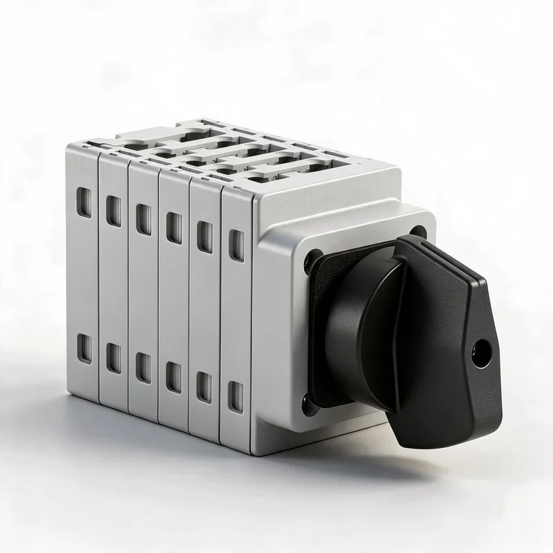
The isolation point on the DC side
In a photovoltaic system the RKE is installed between the PV strings (and any battery) and the inverter. It gives a single, lockable point at which the DC circuits can be made dead before any work begins.
How to specify the RKE
The code is read left to right: current, mounting, knob and poles. A single code therefore describes the current rating and the complete mechanical arrangement of the switch.
| Position | Meaning | Options | Example |
|---|---|---|---|
| RKE16 – RKE55 | Series and rated thermal current (Ith) | RKE16 = 16 A · RKE25 = 25 A · RKE32 = 32 A · RKE40 = 40 A · RKE55 = 55 A | RKE32 |
| Mounting | How the switch is fixed | R = rear panel, Ø22 mm · D = 35 mm DIN-rail · B = door interlock · E = sealed IP66 enclosure | R |
| Knob | Handle type | P = padlockable · U = plain (non-lockable) | P |
| Poles | Number of poles / PV strings | 2 · 3 · 4 · 6 · 8 | 4 |
RKE32-RP4 = 32 A · rear panel mounting · padlockable knob · 4-pole
2-pole
One PV string — switches the positive and the negative conductor together.
4-pole
Two strings, or one string with separately routed positive and negative conductors.
6-pole
Three strings in a single device — fewer components in the combiner box.
8-pole
Four strings; keeps a multi-string array on one lockable handle.
Panel mounting
Rear-panel version with a Ø22 mm shaft for mounting through a panel or enclosure door.
DIN-rail mounting
35 mm DIN-rail version for fitting inside combiner boxes and cabinets.
Door interlock
Door-interlock version — the enclosure door cannot be opened with the switch ON.
Sealed enclosure
IP66 enclosure version for outdoor mounting at the array.
Padlockable
Knob can be padlocked in the OFF position for lock-out / tag-out.
High current
Rated thermal current of 16 – 55 A across the range.
2P and 4P are the most common versions for PV strings. Also available in the range: RKD32, a compact 32 A DC isolator.
Rated operational current (Ie) per pole
Rated current falls as the working voltage rises, because a longer arc must be broken. The standard versions derate with voltage; the PV-optimised four-pole versions hold their full rating all the way to 1200 V DC.
| Model | Ith | 600 V DC | 800 V DC | 1000 V DC | 1200 V DC |
|---|---|---|---|---|---|
| RKE16 | 16 A | 16 A | 16 A | 9 A | 6 A |
| RKE25 | 25 A | 25 A | 20 A | 11 A | 8 A |
| RKE32 | 32 A | 32 A | 23 A | 13 A | 10 A |
| RKE40 | 40 A | 40 A | 30 A | 20 A | 10 A |
| RKE55 | 55 A | 55 A | 45 A | 25 A | 15 A |
PV-optimised four-pole versions (suffix S / T / B)
| Model | 600 V DC | 800 V DC | 1000 V DC | 1200 V DC |
|---|---|---|---|---|
| RKE16 | 16 A | 16 A | 16 A | 16 A |
| RKE25 | 25 A | 25 A | 25 A | 25 A |
| RKE32 | 32 A | 32 A | 32 A | 32 A |
| RKE40 | 40 A | 40 A | 40 A | 40 A |
| RKE55 | 55 A | 55 A | 55 A | 55 A |
Example: RKE32 in the four-pole S / T / B version is rated 32 A at 1200 V DC. The RKE is rated for the photovoltaic utilisation categories DC-PV1 and DC-PV2. Higher-current versions (2H / 3H / 4H) with additional terminals are available for higher-current, lower-voltage circuits. Values are typical — please confirm against the current datasheet for the exact variant required.
RKE technical data
| Function | DC isolator / disconnector for photovoltaic and DC circuits (load-break isolation) |
| Rated insulation voltage (Ui) | 1500 V |
| Rated operational voltage (Ue) | 600 / 800 / 1000 / 1200 V DC |
| Conventional thermal current (Ith) | 16 – 55 A |
| Utilisation category | DC-PV1 / DC-PV2 |
| Poles | 2 · 3 · 4 · 6 · 8 |
| Contact distance (per pole) | 8 mm |
| Polarity | Non-polarised — either polarity may be connected |
| Handle | Rotary knob; padlockable in the OFF position (P versions) |
| Terminal screws | M4 · tightening torque 1.2 – 1.8 N·m |
| Cable cross-section | 4 – 16 mm² (solid / stranded) · 4 – 10 mm² (flexible) |
| Overvoltage category | III |
| Pollution degree | 3 |
| Mechanical life | 10,000 cycles |
| Degree of protection | IP66 for the sealed enclosure version; the panel-mount mechanism is for installation inside a suitable enclosure |
| Mounting | Rear panel (Ø22 mm) · 35 mm DIN-rail · door interlock · sealed enclosure |
| Standards | IEC/EN 60947-3 · GB/T 14048.3 |
| Marking | CE |
Four ways to mount the RKE
The same switch body is offered with different mountings, so the RKE can be fitted at the array, inside a combiner box, on a cabinet door or in a sealed enclosure outdoors.
Rear panel
Mounts through a Ø22 mm hole in a panel or enclosure door with a locknut.
35 mm DIN-rail
Snaps onto standard DIN-rail inside combiner boxes and cabinets.
Door interlock
The door cannot be opened while the switch is ON.
Sealed enclosure
IP66 enclosure version for outdoor mounting at the array.
| Poles | Rear-panel Ø22 mm — body height (mm) | DIN-rail / door — body height (mm) |
|---|---|---|
| 2 | 50.5 | 57.0 |
| 3 | 61.0 | 67.5 |
| 4 / 2H / 4S / 4T / 4B | 71.5 | 78.0 |
| 6 / 3H | 92.5 | 99.0 |
| 8 / 4H | 113.5 | — |
Why a dedicated DC isolator
Purpose-built for DC
A DC arc does not self-extinguish at a current zero as an AC arc does. The RKE uses a long contact gap and a DC-rated breaking construction, so it can safely break a loaded PV string.
Non-polarised
The terminals are non-polarised, so either conductor may be connected to either side — simpler wiring and fewer mistakes on site.
8 mm contact gap
A generous 8 mm contact distance per pole gives a clear, visible isolation gap for safe working.
Padlockable in OFF
The rotary knob can be locked in the 0 (OFF) position with a padlock for lock-out / tag-out during maintenance.
Designed for PV voltages
Rated for 600, 800, 1000 and 1200 V DC systems — covering modern string voltages with margin.
2 to 8 poles
A single device can isolate one string or up to four, keeping the combiner box simple.
Generous terminals
M4 terminals accept 4 – 16 mm² solid or stranded cable, so larger string cables are no problem.
Sealed enclosure option
The enclosure version is IP66 and can be mounted outdoors at the array, close to the strings.
Door-interlock version
Prevents an enclosure being opened while the switch is still ON — a simple mechanical safety function.
10,000 mechanical cycles
A robust cam-and-contact mechanism for a long, maintenance-free service life.
Where the RKE is used
From the DC input of a single string inverter to a utility-scale plant, the RKE provides the lockable DC isolation point that installers and service engineers rely on — including the switch integrated inside inverters and combiner boxes.
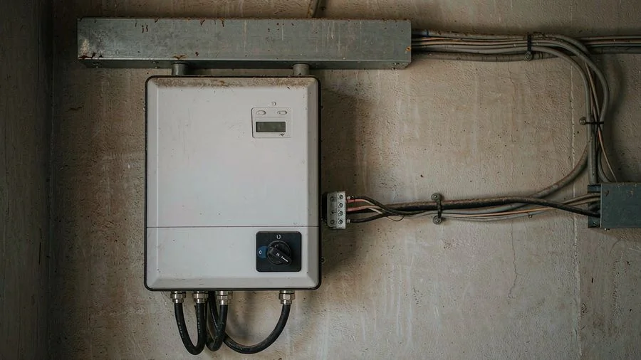
Inverters and DC combiner boxes
The RKE is the switch built into the DC input of string and central inverters, and mounted inside DC combiner boxes — the integrated isolator that makes an inverter safe to service.

Residential rooftop PV
The RKE is fitted on the DC side between the rooftop array and the inverter — usually at the inverter itself or in a dedicated enclosure on the roof.
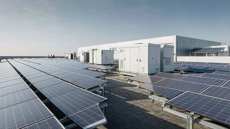
Commercial and industrial PV
On larger rooftop and ground-mounted arrays, one lockable RKE per string or sub-array gives installers a single point of isolation.
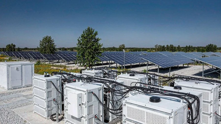
Battery energy storage
In PV-plus-storage systems the RKE isolates the battery and the DC bus from the inverter for commissioning, service and emergency shutdown.

Solar carports and EV charging
DC arrays feeding solar carports and charging hubs are isolated at the array side, so the charging equipment can be serviced safely.
Utility-scale PV plants
String and array isolation in large ground-mounted plants and tracker systems.
Solar pumping
Isolation of the DC array from the pump inverter for irrigation and water supply.
Off-grid and telecom
Safe isolation of DC generation and battery banks at remote and telecom sites.
String combiner boxes
Mounted inside combiner boxes to isolate individual strings before maintenance.
DC distribution and battery cabinets
Load-break isolation of DC feeders and battery strings in cabinets and racks.
Maintenance and emergency isolation
A single lockable point of isolation for installers, service engineers and the fire service.
DC fast-charging piles
DC circuit isolation inside fast-charging cabinets and charging posts.
Inverter DC input
The integrated DC switch on the DC input of string and central inverters.
Application photographs are illustrative and show typical installations; they do not depict a specific project.
Frequently asked questions
Where is a DC isolator installed?
On the DC side of the system — between the PV strings (and any battery) and the inverter. In many installations it is fitted at the inverter, or in an IP66 enclosure at the array.
Why not use an ordinary AC switch?
An AC arc is extinguished naturally as the current passes through zero twice per cycle. DC has no such zero crossing, so the arc keeps burning: a DC switch needs a longer contact gap and an arc-breaking construction. Plugging an AC switch into a DC circuit is unsafe.
Is the RKE polarised?
No. The terminals are non-polarised, so either polarity may be connected to either side of each pole.
Can it be locked off?
Yes. The knob of the P (padlockable) versions can be locked in the OFF position with a padlock for lock-out / tag-out.
What do DC-PV1 and DC-PV2 mean?
They are the two utilisation categories defined for photovoltaic DC circuits in IEC/EN 60947-3 — DC-PV1 for the basic PV switching case and DC-PV2 for the more severe conditions. The RKE is rated for both categories.
What cable can be connected?
4 – 16 mm² solid or stranded, or 4 – 10 mm² flexible cable, using M4 terminals tightened to 1.2 – 1.8 N·m.
What is the degree of protection?
The sealed enclosure version is IP66. The panel-mount mechanism is intended to be installed inside a suitable enclosure.
Which standards apply?
IEC/EN 60947-3 and GB/T 14048.3, utilisation categories DC-PV1 and DC-PV2, marked CE.
Need the right DC isolator for your system?
Tell us the system voltage, the number of strings, the rated current and how you want to mount it — our team will confirm the exact RKE code and can supply samples or OEM versions.
Request a Quote Download Datasheet (PDF)